Tuesday, July 29, 2014

Transformers: The Best Special Effects Ever?
Behind the high-tech scenes of this nerd-proof blockbuster with the geeks who turned blazing concept cars into galaxy-saving Autobots.

More than 750 parts stretching a half-mile long. Some 350 engineers working round-the-clock. Thousands of rusty, old mechanic photos — clutch plates, transmissions, brake discs — spilling across the table. All for one beat-up Camaro? Sure doesn't sound like your average auto manufacturer.
"The idea is they're not fresh off the showroom floor," says Jeff White, the man charged with creating the yellow sports car and 13 others for a big new garage. He's right: They're supposed to look realer than that. And be from outer space. And turn into 30-ft. robots. And save the universe.
That's all in a day's work for the motor magicians at George Lucas's Industrial Light & Magic (ILM), who for the last two years have been juggling the limits of the possible (turning a real car into a fake robot and figuring out what the heck to put inside) and the demands of reality (studio budgets, GM sponsorship, the wrath of fanboys worldwide) to build the most painstaking — and maybe most believable — effects achievement in movie history: Transformers.
When it revs up at the box office this Fourth of July, Michael Bay's $150 million adaptation of the legendary 1980s cartoon and toy series will include nearly 50 so-called transformations. Hand-rendered metallic uncorkings of real-life cars, trucks and helicopters represented uncharted territory for the gooey-alien experts at ILM, each transformation taking six months to imagine and each re-engineering the way digital Hollywood does computer graphics imagery (CGI).
"How are we gonna get this thing from a car into the robot and back in a believable way?" White, the film's digital production supervisor, asked the Transformers crew in 2005, when, after their back-and-forth with toymaker Hasbro, the F/X plan consisted of little more than robot sketches and shiny new Hummers — and not much in between. "Of course, Michael Bay wants a lot of energy, he wants ninja-fighting warriors that can punch and put their arms over their heads and do all this crazy stuff," White says. "So we had to design these really complicated systems — how do all these systems match together and fly over each other to keep it looking real? And that was a huge challenge."
ILM designed a backwards interface, moving the beginning of CGI production out of the hands of creature development and onto the desktops of the animators. By allowing animators to get the first crack at rigging control — the way a computer-generated character is built, the way it walks and rotates — ILM's IT team could develop software for custom transformations designed on the fly that might satisfy Bay's notorious flying camera angles. Click a button here, and a flatbed's brake light can pivot into an Optimus Prime punch. Set a control function there, and an alien jetfighter wing can cock into a Megatron claw for any of a half-dozen different scenes.
For a character like Bumblebee, hiding untransformed inside that '74 Camaro as the shy protector of the movie's human hero, this tradeoff was crucial: the stand-up robot with feelings and the boy's beat-up car with rust were set in stone, so it was the hybrid halfway point that would represent the real character development.
"We start with the end result first, then work backwards from there," says animation supervisor Scott Benza. "We'll start Bumblebee standing up in his pose in the composition of the shot, then collapse him down into something of a car shape, where we fold his arms in and hover him down close to the street. And then we deal with what we have to fill in the in-between."

When it came to breathing life into characters such as Bumblebee, the protective Autobot, ILM needed to think backwards to fill in the blanks (and the junk in the drunk) between finished robot sketches and real-life GM cars.
It started with ILM's creature development team (well versed in children's movie animals but not so much in carburetors) heading to the autobody shop in early 2006 and lifting up the hoods of real-life cars to develop as many real-looking car parts as possible. These formed the innards underneath the exoskeleton provided to the animators. But building a design system that allowed the animators to move all those pieces quickly — and to fit them into the finished robot, designed almost a year earlier, without banging parts into each other — was the real headache.
The 30-year-old Camaro grille, then, may not have been the exact one that ended up on Bumblebee's chest, but it wasn't for lack of trying. Visual effects art director Alex Jaeger built frame-by-frame movements so an animator could take a thinly slatted grille and flip it into a three-slat grille like Venetian blinds. That way, at least, Bumblebee would become both muscular and recognizable (he takes seven different forms — used car, concept car and battered bot among them). Toying with the classic Camaro aside, this hero's transformation represented a massive CGI maneuver, with nearly 20,000 nodes in the movable rig: Jaeger had to break apart a fender close to the ground to unleash Bumbleebee's arm, then disassemble a brake disc attached to the arm before shifting out of the way that will eventually end up on his shoulder.
And Jaeger couldn't screw up. Not while he was working for the guy who reignited Pearl Harbor, who told Bruce Willis how to nuke an asteroid from a space shuttle. No way. "Michael's a very, very particular person when it comes to..." Jaeger trails off. Better be careful with Boss Bay. "This is a man who's shot many a car commercial, so he's very particular on the finishes and the materials on the cars as well as the robots."

But the most important finishing touch? Grease. Lots of it. Sure, stagehands dusted off the real Pontiac Solstice GXP before the cameras rolled, but digital painters at ILM were shading the doors and really mucking up each car's gearbox guts before they rolled up into robots. "Here we've got a car but we don't have any robots, so that's what made this project way harder than Pearl Harbor, where we had real planes to look at," says Ron Woodall, admitting that he painted some cars to look twice as dirty as their exteriors. "We don't have a target, and it's up to everyone's imagination."
Ultimately, that's the point of spending $150 million on car chases, explosions and millions of little CGI polygons: Drummed-up digital trickery is now at the level of turning the unreal into the real — as long as it doesn't seem too cheesy, and doesn't piss off too many fans. "Our goal is to please Michael Bay. He's got to answer to all the other folks," Benza says. "So top of the priority list? If it looks cool, that's where we start. That's the ultimate goal, then we can figure out ways to get the Chevy logo visible and the kind of signature things that the GM folks wanted in there. But I think ultimately even GM wanted Michael to have creative control over the coolness of the transformations."
What ends up on the silver screen this week is something that for once actually looks silver, justifiably chrome. Bay even had to send back one of the few non-CGI scale models made for the film — a painted fiberglass Bumblebee made for a scene when the Autobot savior is tied to train tracks — because it didn't look real enough. "It's been a struggle for all of us in this business to get the computer graphics looking as good as they are now, and I really do believe Transformers is a new high-water mark for making materials look good," says Farrar, the visual-effects supervisor and Bay's right-hand computer geek. "It's surprisingly complicated in the world of computer graphics to make objects look like what everybody in the world sees every day."

For a pivotal fight scene between Bonecrusher (left) and Optimus Prime, the layout team at Industrial Light & Magic used custom software to track a CGI version of the film camera (top). To continue with real-time, on-the-fly transformations, animators work with lower-resolution renders (middle) and coordinate with the creature development team to match up machinery and slot the digital wizardry back into the final cut (bottom).
More than 750 parts stretching a half-mile long. Some 350 engineers working round-the-clock. Thousands of rusty, old mechanic photos — clutch plates, transmissions, brake discs — spilling across the table. All for one beat-up Camaro? Sure doesn't sound like your average auto manufacturer.
"The idea is they're not fresh off the showroom floor," says Jeff White, the man charged with creating the yellow sports car and 13 others for a big new garage. He's right: They're supposed to look realer than that. And be from outer space. And turn into 30-ft. robots. And save the universe.
That's all in a day's work for the motor magicians at George Lucas's Industrial Light & Magic (ILM), who for the last two years have been juggling the limits of the possible (turning a real car into a fake robot and figuring out what the heck to put inside) and the demands of reality (studio budgets, GM sponsorship, the wrath of fanboys worldwide) to build the most painstaking — and maybe most believable — effects achievement in movie history: Transformers.
When it revs up at the box office this Fourth of July, Michael Bay's $150 million adaptation of the legendary 1980s cartoon and toy series will include nearly 50 so-called transformations. Hand-rendered metallic uncorkings of real-life cars, trucks and helicopters represented uncharted territory for the gooey-alien experts at ILM, each transformation taking six months to imagine and each re-engineering the way digital Hollywood does computer graphics imagery (CGI).
"How are we gonna get this thing from a car into the robot and back in a believable way?" White, the film's digital production supervisor, asked the Transformers crew in 2005, when, after their back-and-forth with toymaker Hasbro, the F/X plan consisted of little more than robot sketches and shiny new Hummers — and not much in between. "Of course, Michael Bay wants a lot of energy, he wants ninja-fighting warriors that can punch and put their arms over their heads and do all this crazy stuff," White says. "So we had to design these really complicated systems — how do all these systems match together and fly over each other to keep it looking real? And that was a huge challenge."
Under-prepared, a New Road Map
From Jar Jar Binks in the new Star Wars films to villains of the Pirates of the Caribbean trilogy, the modern CGI pipeline has tended to work from the ground up: Pre-build a creature, film it with a stand-in on set, then animate it to react, to actors such as Samuel L. Jackson or Johnny Depp, in postproduction. But after realizing that the simple route, with one transformation per Autobot or Decepticon, might not look robotic enough, Bay and Co. pulled a 280-terabyte U-turn.ILM designed a backwards interface, moving the beginning of CGI production out of the hands of creature development and onto the desktops of the animators. By allowing animators to get the first crack at rigging control — the way a computer-generated character is built, the way it walks and rotates — ILM's IT team could develop software for custom transformations designed on the fly that might satisfy Bay's notorious flying camera angles. Click a button here, and a flatbed's brake light can pivot into an Optimus Prime punch. Set a control function there, and an alien jetfighter wing can cock into a Megatron claw for any of a half-dozen different scenes.
For a character like Bumblebee, hiding untransformed inside that '74 Camaro as the shy protector of the movie's human hero, this tradeoff was crucial: the stand-up robot with feelings and the boy's beat-up car with rust were set in stone, so it was the hybrid halfway point that would represent the real character development.
"We start with the end result first, then work backwards from there," says animation supervisor Scott Benza. "We'll start Bumblebee standing up in his pose in the composition of the shot, then collapse him down into something of a car shape, where we fold his arms in and hover him down close to the street. And then we deal with what we have to fill in the in-between."
When it came to breathing life into characters such as Bumblebee, the protective Autobot, ILM needed to think backwards to fill in the blanks (and the junk in the drunk) between finished robot sketches and real-life GM cars.
Under the Hood, the Superunknown
When that crucial "in-between" involves over 10,000 hand-modeled parts pulled out of actual autobody — as Optimus Prime did (his old-school toy had a mere 51 components) — there's a bit more filling in to do. "It's hugely complicated," says visual effects supervisor Scott Farrar. "It's no different than going out and machining these parts [in a real car]. Every one of those things has to be connected and travel in the right direction when an animation occurs."It started with ILM's creature development team (well versed in children's movie animals but not so much in carburetors) heading to the autobody shop in early 2006 and lifting up the hoods of real-life cars to develop as many real-looking car parts as possible. These formed the innards underneath the exoskeleton provided to the animators. But building a design system that allowed the animators to move all those pieces quickly — and to fit them into the finished robot, designed almost a year earlier, without banging parts into each other — was the real headache.
The 30-year-old Camaro grille, then, may not have been the exact one that ended up on Bumblebee's chest, but it wasn't for lack of trying. Visual effects art director Alex Jaeger built frame-by-frame movements so an animator could take a thinly slatted grille and flip it into a three-slat grille like Venetian blinds. That way, at least, Bumblebee would become both muscular and recognizable (he takes seven different forms — used car, concept car and battered bot among them). Toying with the classic Camaro aside, this hero's transformation represented a massive CGI maneuver, with nearly 20,000 nodes in the movable rig: Jaeger had to break apart a fender close to the ground to unleash Bumbleebee's arm, then disassemble a brake disc attached to the arm before shifting out of the way that will eventually end up on his shoulder.
And Jaeger couldn't screw up. Not while he was working for the guy who reignited Pearl Harbor, who told Bruce Willis how to nuke an asteroid from a space shuttle. No way. "Michael's a very, very particular person when it comes to..." Jaeger trails off. Better be careful with Boss Bay. "This is a man who's shot many a car commercial, so he's very particular on the finishes and the materials on the cars as well as the robots."
These finished renders of (from left) Autobots Bumblebee and Optimus Prime and Decepticon leader Megatron — filled with hundreds of real aftermarket auto parts — took tens of thousands of pivot points each, with some 10,000 separate pieces to put together Prime alone. (Click here for high-resolution image.)
Under the Gun, the Finishing Brushes
Optimus Prime has lips. Moving metal lips. The Autobot leader went to the grave in the original 1986 movie without ever having opened his voice box, but Bay hated the idea of action heroes wearing a mask. So he had ILM juice up each robot's jaws, eyes and metallic visage, from cartoony strobe light to winking, blinking, crackling Norelco blades.
But the most important finishing touch? Grease. Lots of it. Sure, stagehands dusted off the real Pontiac Solstice GXP before the cameras rolled, but digital painters at ILM were shading the doors and really mucking up each car's gearbox guts before they rolled up into robots. "Here we've got a car but we don't have any robots, so that's what made this project way harder than Pearl Harbor, where we had real planes to look at," says Ron Woodall, admitting that he painted some cars to look twice as dirty as their exteriors. "We don't have a target, and it's up to everyone's imagination."
Ultimately, that's the point of spending $150 million on car chases, explosions and millions of little CGI polygons: Drummed-up digital trickery is now at the level of turning the unreal into the real — as long as it doesn't seem too cheesy, and doesn't piss off too many fans. "Our goal is to please Michael Bay. He's got to answer to all the other folks," Benza says. "So top of the priority list? If it looks cool, that's where we start. That's the ultimate goal, then we can figure out ways to get the Chevy logo visible and the kind of signature things that the GM folks wanted in there. But I think ultimately even GM wanted Michael to have creative control over the coolness of the transformations."
What ends up on the silver screen this week is something that for once actually looks silver, justifiably chrome. Bay even had to send back one of the few non-CGI scale models made for the film — a painted fiberglass Bumblebee made for a scene when the Autobot savior is tied to train tracks — because it didn't look real enough. "It's been a struggle for all of us in this business to get the computer graphics looking as good as they are now, and I really do believe Transformers is a new high-water mark for making materials look good," says Farrar, the visual-effects supervisor and Bay's right-hand computer geek. "It's surprisingly complicated in the world of computer graphics to make objects look like what everybody in the world sees every day."
Director Michael Bay and his $150-million budget weren't about to have Optimus Prime talking through a strobe-like voice box. "If you're gonna watch a movie for two hours, it's kind of boring if you don't see something move," says visual effects supervisor Scot Farrar.
Monday, July 28, 2014
The Dos and Don’ts of Creating Your Demo Reel

Image Source: www.thegnomonworkshop.com
High quality Environment rendering by David Lesperance
High quality Environment rendering by David Lesperance
First, who will be viewing your demo reel.
When filing an application with a company to try and be hired, it is important to firstly read all of their specific directions. It would be wise to do this before final edits of your demo reel have been made. If you have specific companies you wish to be employed by, then first step is looking up what their process and guidelines are. These guidelines will help direct your demo reel, and let you know if there are any formats they do not accept. Sometimes the human resources department will simply email out the links for peoples portfolios with their forwarded resumes and cover letters. Other times, the department heads will request DVDs, so they can all get together and view the work at the same time. When department heads take time out of their schedule to review a possible candidate, they usually look at more than one. They will have a stack of resumes, cover letters, and DVD’s, and most likely want to be as efficient as they can, so they can go back to the work the more thoroughlyenjoy
Second, let’s talk quality.
Your demo reel is to show the great and amazing work you have created, not the ‘kind of ok’ doodle you did during lunch on a greasy napkin. The quality of the work needs to be of your highest caliber, and nothing less. The first work shown on the reel should be your best. The people looking at these reels do not want to wait through lesser work to see your best. Saving the best for last gets your video stopped and ejected before it’s ever seen. This also means dropping any quality of work not deemed to be the same level as your best. A shorter higher quality reel is better than a longer mediocre one.The advantage to sending companies DVDs of your work is the quality of the video can remain high without having to be compressed for online viewing. The disadvantage is that they have to actually open a box and put a disc in a drive. Different companies have different preferences so make sure you double check what they want.
Third, it’s all about you.
It may sound silly but people often times forget who they are, or at least forget to put who they are on their demo reel. There should be an opening slide that has all of your contact information.There should also be a slide before each piece shown to explain what your contribution to the piece was. If it’s an animation of a car burning rubber and sparks and smoke, there needs to be a slide listing what YOU did with what software. “Modeled Car using Maya, applied Mental Ray shaders and Rendered in Mental Ray.”

Image Source: www.cgterminal.com
Still Shot of Visual Effects Breakdown by Josh Clos
Still Shot of Visual Effects Breakdown by Josh Clos
The demo reel ends with a repeat of your identification slide, and keeps it up there longer than the first time to allow people enough time to see it and write your info down.
Finally, double check everything.
Creating a demo reel tends to be the last thing done when graduating from school, or done hastily when you are unexpectedly looking for work. The demo reel is a reflection of your work and your capabilities, and that includes how the demo reel itself is presented. The VFX, film, and video game industries are all very visual, so if you make sure you work is your best, and it’s presented in an aesthetically pleasing manner, then you are that much closer to landing the job .The 7 Most Common CGI Screw-Ups (Explained)
If you've watched movies in the past 10 years, you've probably at some point complained about horrible CG, because you movie viewers are ungrateful little jackanapes.
Every time CG goes well and blends seamlessly into the movie (I bet you didn't know it was used in Brokeback Mountain), people rave about the amazing acting performances and the wonderful storyline and maybe the great soundtrack, and every time it goes wrong, everyone talks about how CG is terrible and is ruining movies.

I'm not joking, watch the video.
But that's OK, whatever, it's a job, nobody says thank you to accountants and insurance underwriters either. I can't brag to anyone about having worked on The Mummy: Tomb of the Dragon Emperor, but it put food on the table. But you know, as long as we're criticizing crappy CG, I thought maybe you'd like to know more about the details of how each terrible disaster unfolds behind the scenes, and more importantly, who to point fingers at.
Here's some of the more common complaints:
#7. Skin Looks Like Plastic

One of the creepier CG sins is to make skin look like plastic. This was only one of many many things wrong with the Scorpion King character above, who actually only appeared in scorpion king form in The Mummy Returns and not in any of the three movies actually named The Scorpion King, because Hollywood likes to confuse us. (Yes, it had two direct-to-DVD sequels. No, nobody watched them.)
When moviegoers say skin "looks like plastic," it can mean a few things. Sometimes they mean faces are rigid and motionless, as if they were made of hard plastic like some kind of creepy doll, which is usually a rigging problem, which I'll talk about later. Sometimes they mean the skin has the texture of plastic, like their face has been shellacked.

Sure, this was 11 years ago, but let us note that the Rock lent his face to this hilariously shameful visual effect the same year that the first Lord of the Rings movie came out.

They hadn't reached their full potential yet (Gollum comes along in the later movies), but clearly, plastic-Rock-head-pasted-on-monster was not "the best you could expect from CG at the time" by any means.
One of the (numerous) things they would do to make Gollum look much, much less like a bad video game character than the Scorpion King was to make his skin not look like frickin plastic. The person responsible for this is the person who writes the shaders. When a character is modeled, or "sculpted" in 3-D, at first it has no color. When modelers show their work for approval, it usually looks like a statue made of dull gray clay.
In fact, freelancers will sell models at this stage. This one is going for $275 on TurboSquid:

A shader writer is a person who writes a program that tells the computer how to "paint" the model -- not just what colors, but how shiny or dull, how bumpy or smooth, how transparent or reflective it is, depending on a bunch of factors, like whether it's facing you or you're looking at it at an angle. Lots of science.
Skin is made of a lot of layers, so it's really complex, and they were really far from figuring it out back when Toy Story was made, for example, which partially drove the decision to make the movie about a lot of plastic toys and not about humans with skin.
The big breakthrough was a thing called subsurface scattering. Read that linked tutorial if you want to find out more about it, but basically, it accounts for light bouncing around through all the layers of the skin so your character stops looking like the picture on the left and starts looking like the picture on the right:

Sunday, July 27, 2014
Hari Pertama


Hari pertama cuma design menggunakan primitif tool. Camera 1, camera2, camera3 ,camera4. Ruang niaga beserta kelengkapan yang belum lagi diletakkan material. Cabaran seterusnya meletakkan material, texture, bipmap dan rendering menngunakan engine Vray. Harapan besok kerja akan dipermudahkan..

How to create a virtual photo studio
Creative director James Cutler shows how to use 3ds Max and V-Ray elements to create a digital version of a photographic studio.

In this tutorial you will learn how to set up a studio environment for rendering a detailed and reflective watch using 3ds Max and V-Ray.
01. Making the stage
Open t_171_Max-Vray_Start.max from the files accompanying this tutorial. In the top viewport, create a box and adjust the size to 400mm x 400mm x 400mm. Name the box Stage.
Right-click the Move tool and set it to 0 for all axes in Absolute World. Convert the Stage box to an editable poly and select the lower back edge. Chamfer the edge by 100mm and set the segments to 50. Select the top, front and side faces and delete them so you are left with a curved backdrop.
Right-click the Stage then go to Object Properties and under General un-tick Visible To Camera. This will mean that the Stage does not appear in the final render but will still contribute to the scene so that the lighting you set up can bounce off it. Open the Material Editor, create a new V-Ray material and assign it to the Stage. Set the diffuse colour to R1 G1 B1.
Select the Stage and make sure that the object’s colour is different to any colour used on the watch, so that it can be easily selected in Photoshop.
02. Positioning the lights
Under Lights in the Create panel, go to the VRayLight. Turn on Targeted and set Half-Length and Half-Width to 150mm. Drag a plane light out in the viewport; with the light selected, right-click the Move tool and set X to -5.8mm, Y to 13.345mm and Z to 407.078mm.
Select the light target and set X to -5.853mm, Y to 13.345mm and Z to 186.568mm. Name the light Top Light. Turn on Invisible so the light is not seen in the render and increase Shadow Subdivisions to 32.
Create a copy of the light and name it Key Light. Position the light in Absolute World: X -5.853mm, Y -193.52mm, Z 304.437mm. Increase the Multiplier of this light to 100. Create a third copy of the light and name it Low Light. Set up the light in Absolute World: X -39.759mm, Y -38.818mm, Z 58.616mm.
Select the light target and position it in Absolute World: X -3.063mm, Y 24.74mm, Z 186.568mm. Set the multiplier to 50, and change Half-Length to 350mm and Half-Width to 100mm.
03. Use the VRaySoftbox material to simulate real soft boxes
Open the Slate Material Editor. Drag a new VRaySoftBox texture onto the slate and name it Softbox. Set the base colour to R 150, G 150, B 150. Under Hot Spot/Dark Spot tick On and set Outer Radius to 0.6.
Go to Frame and turn it on. Right-click the gradient and choose Load, then locate Frame.grd from the Assets folder.
The grid file tells V-Ray where to put a marker on the gradient ramp and what colour that marker should be; this particular grid file creates a thin black frame around the soft box. Alternatively, you can create your own by manually clicking inside the gradient box. These can also be loaded into other gradients and softbox materials.
Drag and drop the softbox texture into the texture slot of all the lights, and select Instance. Set the resolution to the maximum of 2048. C The higher the resolution, the more samples are generated for brighter areas of the texture, which improves the lighting and reflection.
04. Add aditional direct lighting
Currently the light is just coming from three main sources, which means some parts of the watch will not receive any light or reflection. To fix this, a V-Ray Dome Light can be used together with an HDR image to fill in those gaps, using a technique called Image-Based Lighting (IBL).
The dome light is a direct light that uses importance sampling to trace where the bright areas of the HDR image are, so that it knows where it should apply more samples. Compared with just adding an HDR image in the environment slot, this is a much better solution that gives fast and clean results.
Add a VRayLight into the scene, set the type to Dome and turn off Targeted. It doesn’t matter where the light is placed as long as it is perpendicular to the ground plane, and rotating the light does not affect the texture position – this is controlled via the parameters of the HDRI map. Set the Multiplier to 30 and make sure Invisible is ticked (otherwise you will see the HDR image in the background).
Under Texture, assign a VRayHDRI map and set Resolution to 2048. Drag the VRayHDRI over to the Slate Material Editor, choose Instance and name it Dome HDRI. Load your HDR image: I used 07.hdr from the zbyg HDRI Pack 1. Set the Mapping Type to Spherical so the HDRI texture is mapped correctly to the dome shape. B Then tick Flip Horizontally so that it is facing the right way inside the dome.
05. Positioning the camera and setting up exposure
Under the Create panel in Cameras, select VRay from the drop-down list and add a VRayPhysicalCamera to the scene. Position the camera in Absolute World: X -3.917mm, Y -230.287mm, Z 45.287mm. Then position the Camera Target: X -3.344mm, Y 21.12mm, Z 177.367mm. Set the Film Gate to 20.5mm and the Focal Length to 40mm, and lower the f-number to 5 and Film Speed (ISO) to 60.
Turn Vignetting off to remove the darkened edges effect and set the White Balance to Neutral. Any colour adjustments will be done in post-production, so it is best to start with an image that has a neutral white balance.
06. Adjusting the V-Ray render settings
Go to the Render Setup. In the V-Ray tab under Image Sampler (Antialiasing), set the Antialiasing Filter to Quadratic. This is a blurring filter that helps reduce unwanted harsh edges between objects. These harsh edges usually occur when a pixel is brighter than its neighbours, and can be fixed by either using a blurring filter or clamping the colour to reduce the brightness.
In the adaptive DMC Image Sampler, increase Min Subdivisions to 2 and Max Subdivisions to 6. This will improve the antialiasing and reduce noise. Under Colour Mapping, turn on both Sub-Pixel Mapping and Clamp Output. Set Clamp Level to 3 and turn off Affect Background.
Set Gamma to 2.2 and turn on Don’t Affect Colours (Adaptation Only). This tells V-Ray to do all the calculations using Gamma 2.2, but it will not burn this into the final image. This allows the final render elements to be linear, so that when compositing, they blend together correctly.
Turn on Indirect Illumination and set the secondary GI engine to Light Cache. Under Irradiance Map, set the preset to Medium, and both the HSph Subdivisions and the Interp. Samples to 150. This will improve the quality of the global illumination and reduce splotches. Turn on Show Calculation Phase to see the results during rendering.
Under Light Cache, increase the Subdivisions setting to 1500 and set the number of passes to match the number of processing cores you have available. Turn on Show Calculation Phase. In the Reconstruction parameters, tick Use Light Cache For Glossy Rays. With this option on, the light cache will be used to calculate glossy rays as well as normal GI rays, which can greatly improve render time. Go to the Render Elements tab and add the following render elements: VRayWireColor, VRayGlobalIllumination, VRayLighting, VRaySpecular, VRayReflection, VRayExtraTex, and VRayBackground.
There is no need to add a refraction element: transparency will be included in all the other elements with the glass material being set to All Channels in Refraction. The wire colour element is useful for completing post-production work. It takes the wire colour of the object in 3ds Max and renders out a flat diffuse colour that can be easily selected in Photoshop. This element also has antialiasing so you get the blurred edges from the AA filter.
In the VRayBackground parameters, untick Colour Mapping so that the background image is not affected and remains the same brightness and colour. One of the render passes to include is Ambient Occlusion: by incorporating it into a render element, it is much more efficient. Also, there is no need to turn lights off or hide transparent objects, which is a requirement in some other methods.
Select the VRayExtraTex element and add a VRayDirt map to the texture slot. Drag the VRayDirt map to the Material Editor and choose Instance. Set the Radius to 50mm, the Subdivs to 18 and turn on Work With Transparency. The radius size depends on the scene – the larger the radius, the larger the dirt will spread. So if the radius is too large for a small object, then the size of the ambient occlusion will become too much. The mode is set to Ambient Occlusion by default. Click Exclude and, from the list, select Watch Glass and move it over to the Exclude box on the right.
Go to the V-Ray tab. Under V-Ray, enable the built-in Frame Buffer and untick Get Resolution From Max. Set the Width to 5000 and Height to 3750. Tick Save Separate Render Channels and untick Save Alpha, then locate a folder to store all the render elements in. Select OpenEXR from the Save As Type drop-down; in the EXR, make sure it is set to Half Float (16 bits/channel).
Half Float has enough colour range for compositing, so there’s no need to render in Full Float unless it is required for passes such as Z-Depth. In Environment And Effects, add Chrome_ Background.tif as a background environment map. Now click Render and, in the VRay Frame Buffer, turn on Show sRGB to view the render at the correct gamma. This gamma correction will automatically be applied when opening the EXR files.
07. Compositing the render elements in Photoshop
Close the image and go to File > Scripts, and load all the files into stack. Browse to the Renders folder and select all the render elements. When prompted, choose As Alpha Channel and click OK. If you are not prompted and the layers open with transparency, you need to first open an individual layer and choose As Alpha Channel to set it as the default.
Once the render elements have loaded into the layers stack, move VRayBackground to the bottom of the stack. Then move VRayWireColor, RGB Color and VRayExtraTex to the top and turn themoff.
Select the VRayReflection, VRaySpecular, VRayLighting and VRayGlobalIllumination layers and set the blend mode to Linear Dodge (Add). Check the final composite is correct by turning on the RGB layers to make sure they match.
08. Converting 32-bit to 16-bit in Photoshop
Photoshop opens 16-bit Half Float as 32 bits per channel, and the editing tools do not work at this level. The file needs to be down-converted to 16 bits per channel – but doing so causes all the blending modes to be incorrect, resulting in a blown-out image. To fix this, assign a linear colour profile before converting. VFXForge offers a suitable profile.
In the assets folder, copy the Linear RGB ICC profile to C:\Windows\System32\spool\drivers\color. Then go to Colour Settings under Edit. By default the working space is set to Monitor RGB sRGB IEC61966-2.1: because you composited in Linear, you need to change that to match. In the RGB drop-down, choose Load RGB and browse to the Linear RGB ICC profile.
Click OK and go to Image > Mode > 16 bits/ channel, and select Don’t Merge when prompted. You may notice some colour banding:this is Photoshop not being able to display the image properly when zoomed out. If you zoom in (100%), you will see the correct image.
09. Post-production techniques
Before you do any adjustments such as levels or colour correcting you need to revert back to Monitor RGB sRGB IEC61966-2.1, otherwise any adjustments you make will be using the wrong colour setting. Go to Edit > Colour Settings to change it back to sRGB IEC61966-2.1.
Turn on and select the VRayExtraTex layer, which is the ambient occlusion data. Marquee-select the outer black area and remove it, otherwise it will affect the background layer. Set the blend mode to Multiply – you will notice shadow details will appear that were lost during rendering.
Set the Opacity to around 50%: sometimes too much ambient occlusion can make the render look unrealistic. Select all the layers in the stack apart from the background layer and convert them to a Smart Object. (This allows you to still edit the stack later on if you need to, by double-clicking on the Smart Object to open it.)
Set the Smart Object blend mode to Linear Dodge (Add). Add a Colour Balance adjustment on top and make it only affect the smart object. Set the cyan-red to -5 and the magenta–green to 2.
10. Converting the layered PSD file into an 8-bit image format
If you down-convert to 8-bit from 16-bit, you will notice some colour banding appears in the image. In order to successfully save out an 8-bit image that can be used for the web, first up-convert to 32-bit and choose Rasterize, and then Merge. There is no need to switch colour profiles to do this, so make sure you are still using sRGB IEC61966-2.1.
Now go to Image > Mode and choose 8-bit. Next choose Merge and an HDR toning window will appear. In the Method drop-down list, choose Exposure and Gamma and then click OK without adjusting any of the settings. You can now save out the final render in an 8-bit format, and it’s ready to use for the web.
James Cutler runs MintViz Workshop, the definitive resource for
CG artists, designers and generalists who are looking to develop their technical skills.
CG artists, designers and generalists who are looking to develop their technical skills.
This article originally appeared in 3D World issue 170
Friday, July 25, 2014
Friday, July 18, 2014

Thursday, July 17, 2014
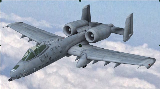
Bell Boeing V22 Osprey

General characteristics
- Crew: Four (pilot, copilot and two flight engineers/crew chiefs)
- Capacity:
- 24 troops (seated), 32 troops (floor loaded), or
- 20,000 lb (9,070 kg) of internal cargo, or up to 15,000 lb (6,800 kg) of external cargo (dual hook)
- Length: 57 ft 4 in (17.5 m)
- Rotor diameter: 38 ft 0 in (11.6 m)
- Wingspan: 45 ft 10 in (14 m)
- Width with rotors: 84 ft 7 in (25.8 m)
- Height: 22 ft 1 in/6.73 m; overall with nacelles vertical (17 ft 11 in/5.5 m; at top of tailfins)
- Disc area: 2,268 ft² (212 m²)
- Wing area: 301.4 ft² (28 m²)
- Empty weight: 33,140 lb (15,032 kg)
- Loaded weight: 47,500 lb (21,500 kg)
- Max. takeoff weight: 60,500 lb (27,400 kg)

Performance
- Maximum speed: 275 knots (509 km/h, 316 mph[229]) at sea level / 305 kn (565 km/h; 351 mph) at 15,000 ft (4,600 m)[230]
- Cruise speed: 241 kn (277 mph, 446 km/h) at sea level
- Stall speed: 110 kn[52] (126 mph, 204 km/h) in airplane mode
- Range: 879 nmi (1,011 mi, 1,627 km)
- Combat radius: 390 nmi (426 mi, 722 km)
- Ferry range: 1,940 nmi (2,230 mi, 3,590 km) with auxiliary internal fuel tanks
- Service ceiling: 25,000 ft (7,620 m)
- Rate of climb: 2,320 – 4,000[52] ft/min (11.8 m/s)
- Glide ratio: 4.5:1[52]
- Disc loading: 20.9 lb/ft² at 47,500 lb GW (102.23 kg/m²)
- Power/mass: 0.259 hp/lb (427 W/kg)
Armament
- 1× 7.62 mm (0.308 in) M240 machine gun or 0.50 in (12.7 mm) M2 Browning machine gun on ramp, removable
- 1× 7.62Performance
- Maximum speed: 275 knots (509 km/h, 316 mph[229]) at sea level / 305 kn (565 km/h; 351 mph) at 15,000 ft (4,600 m)[230]
- Cruise speed: 241 kn (277 mph, 446 km/h) at sea level
- Stall speed: 110 kn[52] (126 mph, 204 km/h) in airplane mode
- Range: 879 nmi (1,011 mi, 1,627 km)
- Combat radius: 390 nmi (426 mi, 722 km)
- Ferry range: 1,940 nmi (2,230 mi, 3,590 km) with auxiliary internal fuel tanks
- Service ceiling: 25,000 ft (7,620 m)
- Rate of climb: 2,320 – 4,000[52] ft/min (11.8 m/s)
- Glide ratio: 4.5:1[52]
- Disc loading: 20.9 lb/ft² at 47,500 lb GW (102.23 kg/m²)
- Power/mass: 0.259 hp/lb (427 W/kg)
Armament- 1× 7.62 mm (0.308 in) M240 machine gun or 0.50 in (12.7 mm) M2 Browning machine gun on mm (.308 in) GAU-17 minigun, belly-mounted, retractable, video remote control in the Remote Guardian System [optional][
Wednesday, July 16, 2014
Tokyo-Based Artist Arrested For 3D Printing Her Vagina
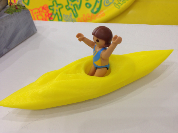
The files in question are, to be clear, fairly stylized representations of the female form, as is most of her art. Igarashi, who calls herself Rokudenashi-ko or “Good-For-Nothing Girl,” began making the prints when she decided to explore her own sexuality and the role of the female form in Japanese culture. While the male member is not as taboo in Japanese culture (NSFW example), the female genitals are all but hidden.
“As an artist, I focus on my own vagina as the motif for my art,” she wrote. “My work is against discriminative / ignorant treatment of the vagina.”
“I cannot understand why the police recognize the 3D data as obscene material,” she said.
Her fundraising goal was to raise money to build something called the Manko-boat or Manbo, essentially “pussy boat,” based on the shape of her vagina. Her charmingly innocuous pitch video appears below.
The question this arrest raises, obviously, is what can be defined as obscenity, especially in regard to self-scanning, 3D printing, and art. No rational person would mistake Igarashi’s work with pornography but, clearly, she is not dealing with rational people. In the end, control over her body and her image is solely hers and, I suspect, art will win out.
Brilliant VFX whip up a storm
A seamless combination of video and 3D animation sees a young boy encounter a sea storm in this thrilling new ad. We find out how it was made.
http://youtu.be/qXUnqQ-Er-M
Insurance company Delta Lloyd recently commissioned advertising agency TBWA\NEBOKO to create this new spot, which features the voyage of a young boy, who negotiates the elements of the ocean on a small boat.
Along his journey, he encounters seals, a storm, vortex and huge whale, all of which were created by French post production house Digital District. " 'Storm in the open sea' were the first words we heard about the film," says FX supervisor Thomas Marqué.
Naiad also provided the solution to the team's biggest challenge. "The sea surface becomes more complex in a storm, a little swash turn into a very detailed mountain full of foam and sea sprays," says FX lead Marc Thomas Cavé.

Fluid simulation software Naiad provided the Digital District team with the solution to all their sea simualtion issues
"For the surface itself, we used a NOT-ocean mesh in Naiad to create the main surface. This object is very sharp and detailed and acted as our base to work on foam, splashes, sprays and wakes. It's also the reference surface for the animator in charge of the boats. Naiad is powerful enough to make particles collide on such detailed meshes - it was a vital piece of software on this project."
http://youtu.be/qXUnqQ-Er-M
Insurance company Delta Lloyd recently commissioned advertising agency TBWA\NEBOKO to create this new spot, which features the voyage of a young boy, who negotiates the elements of the ocean on a small boat.
Along his journey, he encounters seals, a storm, vortex and huge whale, all of which were created by French post production house Digital District. " 'Storm in the open sea' were the first words we heard about the film," says FX supervisor Thomas Marqué.
The goal was simple - make it real
Naiad also provided the solution to the team's biggest challenge. "The sea surface becomes more complex in a storm, a little swash turn into a very detailed mountain full of foam and sea sprays," says FX lead Marc Thomas Cavé.
Fluid simulation software Naiad provided the Digital District team with the solution to all their sea simualtion issues
"For the surface itself, we used a NOT-ocean mesh in Naiad to create the main surface. This object is very sharp and detailed and acted as our base to work on foam, splashes, sprays and wakes. It's also the reference surface for the animator in charge of the boats. Naiad is powerful enough to make particles collide on such detailed meshes - it was a vital piece of software on this project."


Monday, July 7, 2014


Sunday, July 6, 2014


Sunday, June 29, 2014


Saturday, June 28, 2014
Thursday, June 19, 2014
ANIMATORS IN ACTION The Hobbit: The Desolation of Smaug
Hollywod production, Hobbit The Desolation of Smaug how they make
attention for mocap suite
Friday, June 13, 2014
Sunday, June 8, 2014
Thursday, May 29, 2014
Monday, May 26, 2014
Sunday, May 25, 2014
Saturday, May 24, 2014
Friday, May 16, 2014
Thursday, May 15, 2014
Wednesday, May 14, 2014
Tuesday, May 13, 2014

Monday, May 12, 2014
Saturday, May 10, 2014
Wednesday, May 7, 2014
Tuesday, May 6, 2014
Monday, May 5, 2014
LOD continued
Although the algorithm introduced above covers a whole range of level of detail management techniques, real world applications usually employ different methods according the information being rendered. Because of the appearance of the considered objects, two main algorithm families are used.[3]
The first is based on subdividing the space in a finite number of regions, each with a certain level of detail. The result is discrete number of detail levels, from which the name Discrete LoD (DLOD). There's no way to support a smooth transition between LOD levels at this level, although alpha blending or morphing can be used to avoid visual popping.
The second considers the polygon mesh being rendered as a function which must be evaluated requiring to avoid excessive errors which are a function of some heuristic (usually distance) themselves. The given "mesh" function is then continuously evaluated and an optimized version is produced according to a tradeoff between visual quality and performance. These types of algorithms are usually referred as Continuous LOD (CLOD).
Details on Discrete LOD
An example of various DLOD ranges. Darker areas are meant to be rendered with higher detail. An additional culling operation is run, discarding all the information outside the frustum (colored areas).
The basic concept of discrete LOD (DLOD) is to provide various models to represent the same object. Obtaining those models requires an external algorithm which is often non-trivial and subject of many polygon reduction techniques. Successive LOD-ing algorithms will simply assume those models are available.
DLOD algorithms are often used in performance-intensive applications with small data sets which can easily fit in memory. Although out-of-core algorithms could be used, the information granularity is not well suited to this kind of application. This kind of algorithm is usually easier to get working, providing both faster performance and lower CPU usage because of the few operations involved.
DLOD methods are often used for "stand-alone" moving objects, possibly including complex animation methods. A different approach is used for geomipmapping[4], a popular terrain rendering algorithm because this applies to terrain meshes which are both graphically and topologically different from "object" meshes. Instead of computing an error and simplify the mesh according to this, geomipmapping takes a fixed reduction method, evaluates the error introduced and computes a distance at which the error is acceptable. Although straightforward, the algorithm provides decent performance.
A discrete LOD example
As a simple example, consider the following sphere. A discrete LOD approach would cache a certain number of models to be used at different distances. Because the model can trivially be procedurally generated by its mathematical formulation, using a different amount of sample points distributed on the surface is sufficient to generate the various models required. This pass is not a LOD-ing algorithm.
Visual impact comparisons and measurements
Image
Vertices ~5500 ~2880 ~1580 ~670 140
Notes Maximum detail,
for closeups. Minimum detail,
very far objects.
To simulate a realistic transform bound scenario, we'll use an ad-hoc written application. We'll make sure we're not CPU bound by using simple algorithms and minimum fragment operations. Each frame, the program will compute each sphere's distance and choose a model from a pool according to this information. To easily show the concept, the distance at which each model is used is hard coded in the source. A more involved method would compute adequate models according to the usage distance chosen.
We use OpenGL for rendering because its high efficiency in managing small batches, storing each model in a display list thus avoiding communication overheads. Additional vertex load is given by applying two directional light sources ideally located infinitely far away.
The following table compares the performance of LoD aware rendering and a full detail (brute force) method.
Visual impact comparisons and measurements
Brute DLOD Comparison
Rendered
images
Render time 27.27 ms 1.29 ms 21 × reduction
Scene vertices
(thousands) 2328.48 109.44 21 × reduction
Hierarchical LOD
Because hardware is geared towards large amounts of detail, rendering low polygon objects may score sub-optimal performances. HLOD avoids the problem by grouping different objects together[5]. This allows for higher efficiency as well as taking advantage of proximity considerations.
Level of Detail LOD
In computer graphics, accounting for level of detail involves decreasing the complexity of a 3D object representation as it moves away from the viewer or according to other metrics such as object importance, viewpoint-relative speed or position. Level of detail techniques increases the efficiency of rendering by decreasing the workload on graphics pipeline stages, usually vertex transformations. The reduced visual quality of the model is often unnoticed because of the small effect on object appearance when distant or moving fast.
Although most of the time LOD is applied to geometry detail only, the basic concept can be generalized. Recently, LOD techniques also included shader management to keep control of pixel complexity. A form of level of detail management has been applied to textures for years, under the name of mipmapping, also providing higher rendering quality.
It is commonplace to say that "an object has been LOD'd" when the object is simplified by the underlying LOD-ing algorithm.
Sunday, May 4, 2014
Saturday, May 3, 2014
Friday, May 2, 2014
Thursday, April 24, 2014
Tuesday, April 22, 2014
Sunday, April 20, 2014
The Fly Vfx Breakdown by Giulio Tonini
These are five shots I recently worked on. Even house flies drop dead because of boring and bad quality programmes on TV!
I used Maya for the animation, shading and rendering with Arnold Render and Nuke for compositing.
rendering with Arnold Render and Nuke for compositing.


Saturday, April 12, 2014
Hybrids Realflow
Reference to demon wave characteristic
https://www.youtube.com/watch?v=XPrs0H0Adig&feature=youtube_gdata_player
https://www.youtube.com/watch?v=XPrs0H0Adig&feature=youtube_gdata_player
Tuesday, March 11, 2014

Subscribe to:
Posts (Atom)

;)